What part do you need help with? The logic of the device seems pretty straight forward and not requiring a high speed digital interface. The 6008 is static digital I/0 and not capable of high speed operation.
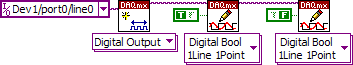
At the simplest, you could create a task for the data pin and a task for the clock signal. Apply the data with a DAQmx Write and then clock it in with a couple of DAQmx Writes (one with True as data in and one with False as data in). Look at the image below. Control of individual lines is about as simple as you can get. You will eventually need additional lines for control but start small and simple.
<img src="
Loading Image...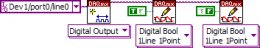
">
Have you gone over the shipping examples to understand how to output data with the DAQmx functions?
p.s. I forgot to connect the error in/error out clusters. They should be connected when you do your program.Message Edited by Dennis Knutson on 07-23-2008 07:57 PM
Basic Digital Write.PNG:
http://forums.ni.com/attachments/ni/250/41784/1/Basic Digital Write.PNG
 ">
">