Paul C.
2007-11-13 21:10:06 UTC
Hi Tao,
Unfortunately, the USB-6008 doesn't have dynamic Digital I/O. You can
only do software timed output. Were you planning on using software
timing to time the digital output non-overlap clocks or were you going
to use external circuits to break up a counter output (digital pulse
train) into the two non-overlapping clocks? I would like to mention
that the accuracy of a software timed clock is system dependent and may
not be possible at millisecond or faster speeds. In addition, I would
like to mention that the speed you could create these clocks would
depend on
the fastest portion of the signal (I'm assuming the point where both
are switched low prior to one going high - essentially, where the lows
overlap).
I also wanted to make sure that I fully understand how you will need to implement the non-overlap clocks. <a href="http://tams-www.informatik.uni-hamburg.de/applets/hades/webdemos/12-gatedelay/40-tpcg/two-phase-clock-gen_print.html" target="_blank">Here</a>
is a picture of how I visualize these clocks. Take a look at the
bottom of the page and tell me if that is what you're going to
implement. Once again are you going to need to generate both of those
pulse trains with a digital output line or are you going to do it with
external circuits (where you provide a clock to it and it splits it
into two clocks)?
I'd also like to mention that it would be fairly simple to build a
LabVIEW program to output a series of 1's and 0's on a line or port.
All you need to do is run a for loop that will index an array and
output a portion of the array every iteration of the loop. For
example, I made a simple example that counts on the digital lines from
0-15 (0000,0001,0010, etc.). The code I used is shown below.<img src="Loading Image...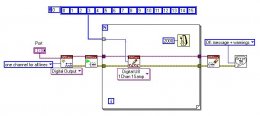 ">
">
I hope this helps you get started,
Paul C.Message Edited by Paul C. on 11-13-2007 02:56 PM
swdigitaloutput2.JPG:
http://forums.ni.com/attachments/ni/250/34855/1/swdigitaloutput2.JPG
Unfortunately, the USB-6008 doesn't have dynamic Digital I/O. You can
only do software timed output. Were you planning on using software
timing to time the digital output non-overlap clocks or were you going
to use external circuits to break up a counter output (digital pulse
train) into the two non-overlapping clocks? I would like to mention
that the accuracy of a software timed clock is system dependent and may
not be possible at millisecond or faster speeds. In addition, I would
like to mention that the speed you could create these clocks would
depend on
the fastest portion of the signal (I'm assuming the point where both
are switched low prior to one going high - essentially, where the lows
overlap).
I also wanted to make sure that I fully understand how you will need to implement the non-overlap clocks. <a href="http://tams-www.informatik.uni-hamburg.de/applets/hades/webdemos/12-gatedelay/40-tpcg/two-phase-clock-gen_print.html" target="_blank">Here</a>
is a picture of how I visualize these clocks. Take a look at the
bottom of the page and tell me if that is what you're going to
implement. Once again are you going to need to generate both of those
pulse trains with a digital output line or are you going to do it with
external circuits (where you provide a clock to it and it splits it
into two clocks)?
I'd also like to mention that it would be fairly simple to build a
LabVIEW program to output a series of 1's and 0's on a line or port.
All you need to do is run a for loop that will index an array and
output a portion of the array every iteration of the loop. For
example, I made a simple example that counts on the digital lines from
0-15 (0000,0001,0010, etc.). The code I used is shown below.<img src="Loading Image...
 ">
">I hope this helps you get started,
Paul C.Message Edited by Paul C. on 11-13-2007 02:56 PM
swdigitaloutput2.JPG:
http://forums.ni.com/attachments/ni/250/34855/1/swdigitaloutput2.JPG
