Diora
2008-08-12 21:40:24 UTC
I have a usb 6259bnc DAQ and want to create close loop control for a dc motor and feedback will be provided by analog sensor. Attached is the main vi of the controller. There are 3 subvi inside the loop: p controller, sensor and pwm. Every time I run the main vi, the while loop will not start next iteration until each subvi finished. I'm using this pwm vi as subvi in the main vi: <a href="http://zone.ni.com/devzone/cda/epd/p/id/5043" target="_blank">http://zone.ni.com/devzone/cda/epd/p/id/5043</a>. Every time I push the stop button in this pwm vi, error pop up. I think 6259 belongs to m series and it should work fine. Is there something I need to do to use this pwm vi? As I mention before, the loop in main vi will not continue unless the sub vi is finished, but in that pwm vi I could not stop it except push the stop button, and once I push the stop button error pop up. Even I could stop the pwm subvi normally, the speed to run the main vi will very slow and not continue because the pwm generation will be stop while other parts are running. So, any good suggestion to build up a close loop control with labview and usb 6259bnc?
Thanks in advance!
Presentation11.gif:
Loading Image...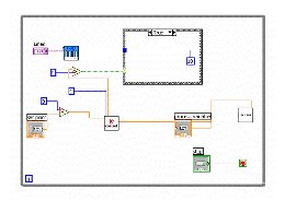
Thanks in advance!
Presentation11.gif:
Loading Image...


